
This information pertains to the PTO unit of IH tractor models 706-1486. The PTO unit on these tractors is a self contained assembly that is bolted to the rear frame of the tractor. The power is transferred to the unit by a constant running shaft which is driven by the clutch pressure plate. The constant running shaft powers a hydraulic pump driven by the input shaft of the PTO unit. (This pump is self contained in the unit and only supplies pressure to the PTO unit). The hydraulic pump supplies oil pressure to a control valve inside the PTO unit housing. When this valve is activated, it directs oil pressure from the pump to a hydraulic piston that when pressurized, engages a clutch pack which drives the output shaft.
This unit can be removed from the rear frame of the tractor for repair. The complete unit needs to be removed, it cannot be disassembled while it's in the tractor. Removal requires draining the transmission/rear housing oil. Removing the 3 point hitch upper link bracket/cover allows access to aid in shaft alignment. The unit can be pulled back enough to disengage the drive shaft, but take care to not damage the oil sump tube which angles down towards the bottom of the rear frame housing. Using 2 of the long bolts that held the unit in the tractor, screw them into the two top rear threaded bolt holes (they will be sticking out the back while unit is still in the tractor). They will act as legs and you can stand the removed unit on them and the 540 output shaft. ( Note Late model 86 series units may not have these taped bolt holes) The input shaft will be pointed straight up.
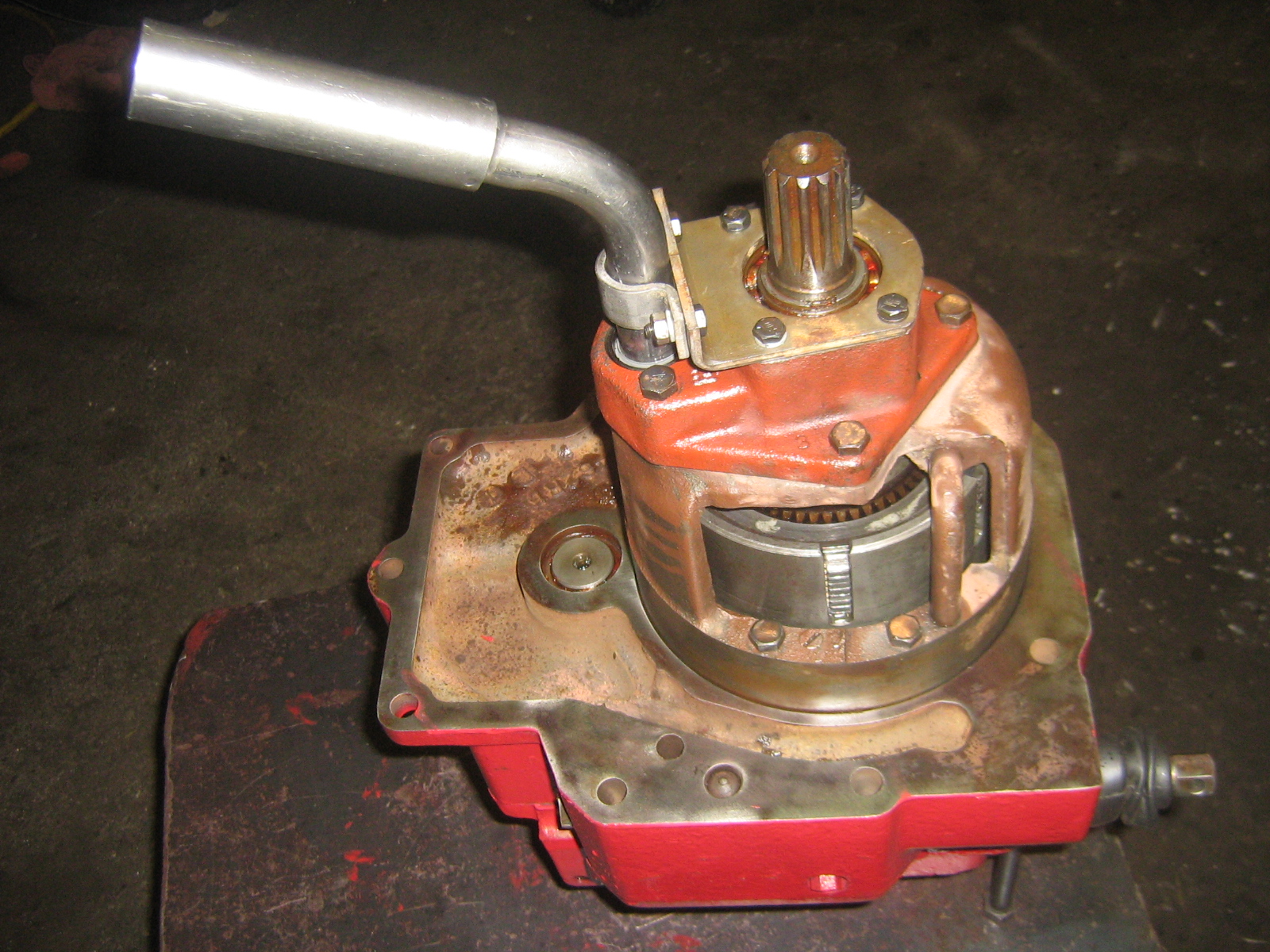 What follows here pertains to the removed PTO unit. Use this information to
replace shafts, brakes, or clutches within the unit. Start by removing
the 4) 3/8" bolts that attach the pump housing to the unit. The pump
housing is bell shaped, and is 7 1/2" in diameter. You may need to jar it loose
with a soft faced hammer. Set it aside, usually no further disassembly is necessary for the pump.
What follows here pertains to the removed PTO unit. Use this information to
replace shafts, brakes, or clutches within the unit. Start by removing
the 4) 3/8" bolts that attach the pump housing to the unit. The pump
housing is bell shaped, and is 7 1/2" in diameter. You may need to jar it loose
with a soft faced hammer. Set it aside, usually no further disassembly is necessary for the pump.
The large snap ring holding the clutch PACK can now be removed along with the clutch PACK. If the clutch PACK is the only parts being replaced no further disassembly is required.

To continue disassembly, the large spring in the center of the clutch carrier needs to be compressed enough to remove the snap ring. This may be done in a press, or by making a simple tool, or you can purchase the tool in my store (seen here)
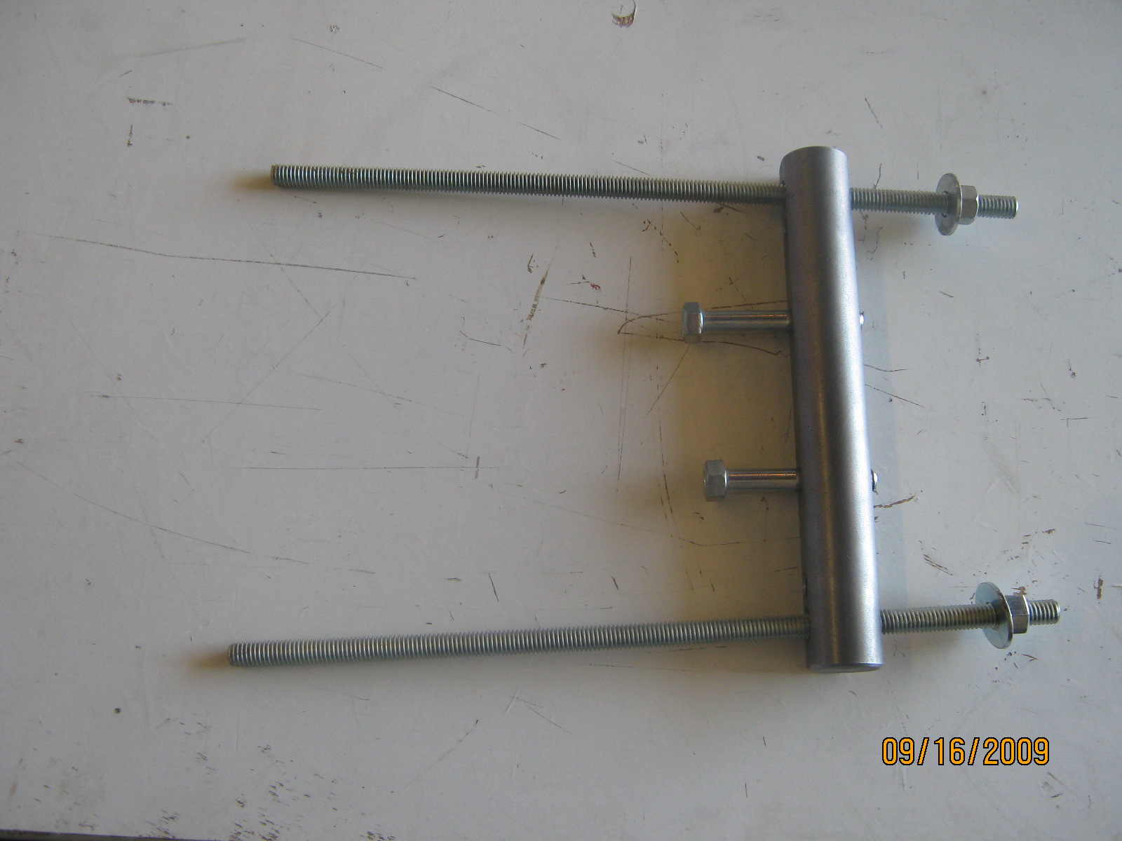
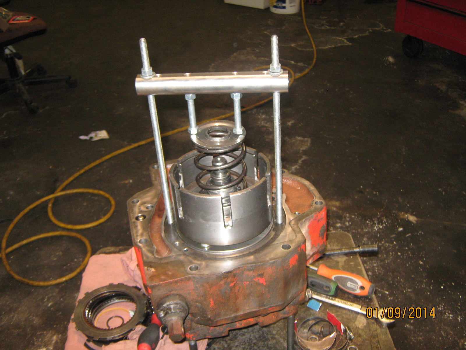
Be careful removing this spring, it should expand to aproximately 5" in length if it is to be used again.
With the spring removed, remove the snap ring above clutch piston. This snap ring is a stop for the clutch piston so it cannot over-stroke if the clutch PACK becomes too worn. (Note: this snap ring is not used on some models). Thread in 2 1/4" X 4"+or- bolts into the threaded holes in the top of the clutch piston. By use of the 2 bolts as handles, pull up with a twisting action to remove the piston. Inspect the outer lip seal and inner o-ring seal on the piston for wear, nicks, or heat damage. These seals should be replaced and are included in the seal and gasket sets I use and sell.


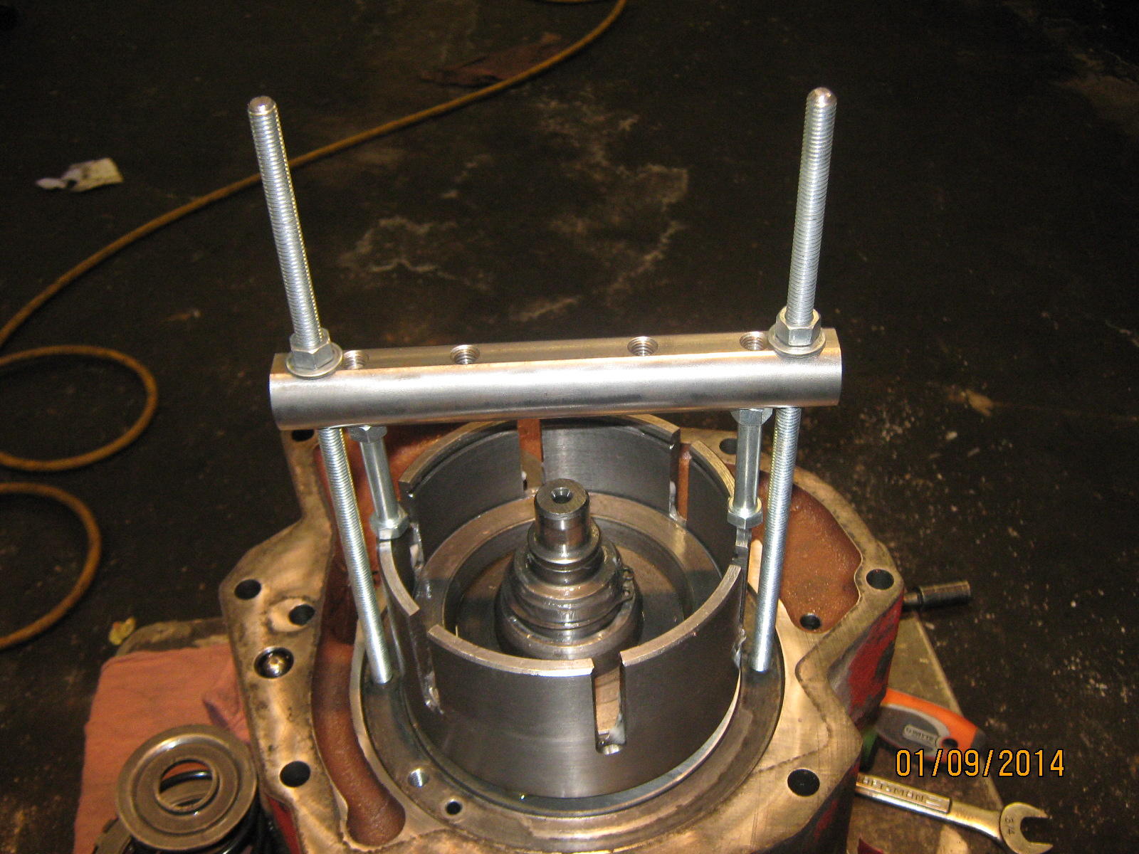
With piston removed, the next step is to compress the brake piston springs that are pushing the clutch carrier up

against the snap ring inside the carrier. You can either use a press again, or the same tool that you made, or the tool that we sell. Basically you need to push the carrier drum down enough to remove the snap ring.
With the snap ring removed, the clutch carrier drum can be pulled up off the splines of the 1000 RPM shaft. The two Teflon seal rings on the drum can be replaced at this time. If they look good (no sign of wear, nicks, or cuts) I leave the old ones in place. (Installing new ones is a procedure in itself. The new ones need to be warmed up in hot water, stretched, installed, and re-compressed).

With the drum removed,

the remaining two bolts holding the rear cover to the valve housing of the unit can now be removed. The spring pressure of the three brake piston springs will push the cover away from the unit valve body as you loosen the two remaining bolts. There are two dowel pins that may hang up the separation process. Lift off the valve body. Inspect the inside bore of the valve body where the 2 teflon seals ride. If there is grooving in the housing it will need to be repaired or replaced.( I offer REMAN housings )Inspect the three brake pistons. There should be at least 3/32" of brake pad material remaining on the end of the pistons, if not they should be replaced. At this point the the idler gear and its two thrust washers can be removed and set aside. Now removal of either of the two shafts, bearings, and seals will be self evident. Just do not damage the outer brass washer next to the 540 seal.
To service the control valve Remove the Hex plug on the bottom of the valve body directly below the valve spool. With the plug removed the valve stem can be pushed down and out through the removed plug hole on the bottom.
Inspect the JUDAS pin that hols the top and bottom of the valve together to make sure it is present and not broken. Replace if necessary. ( If all seals and gaskets and all components of the unit are in good condition and the unit will not build correct pressure, replace the 2 springs on the bottom portion of the valve) I have them in stock but they can be supplied by your local CaseIH dealer as well.
Make sure that the upside down cup/spacer is installed cup down and that it cannot slide past the ledge on the spool
Any questions or comments? You can send me an email and I can help.
Assembly of 2 speed PTO unit
Install the seals. The 1000 RPM shaft seal installs from the rear or outside. The 540 shaft seal installs from inside with brass washer first facing rear or outside of unit. (This is only for protecting the seal). Usually the bearings do not need to be replaced. If new shafts are installed, the bearings will need to be transferred to the new shafts. Install both shafts and bearings with snap rings. Install the gear and spacer on 540 shaft. Install the idler shaft with one thrust washer facing up towards idler gear. Install the Idler gear.
Install the three brake pistons in the valve housing with new o-rings. The three springs will sometimes half-thread, or kind of bind onto the brake pistons. If they don't, then set the springs on their pads on the rear cover (you should have it facing up at this point). Lay a new gasket on the up-side of the rear cover. Replace the thin o-ring on the 1000 RPM shaft. Use a tacky grease stick the back side of the second thrust washer for the idler gear to the valve body, centered over the idler shaft bore with the notch indexed. Now carefully set the valve body down over the 1000 RPM shaft, making sure the brake pistons are entering the inside of the three springs, and also align the 540 shaft and the idler shaft with their respective bores and bearing. At this point the two housings should be close enough together to start the two short cap screws. Slowly draw the bolts in, alternating between them to keep things even. If you feel some resistance it may be the dowel pins. If it does not seem like it's the dowel pins, it could be that the greased thrust washer fell off and you are crushing the index tab. If you used a good tacky grease, and worked the washer around it, is unlikely that it will fall off.
At this point the two halves should be bolted together and the shafts should turn freely and the three brake piston pads should be facing up. The clutch carrier drum can now be installed. If the Teflon seal rings need to be replaced, here is the procedure: Cut or pry the old ones off of the drum. Warm up the new ones in hot water and gently stretch them out just enough to fit over the drum. Using a radiator hose clamp and a thin piece of plastic or cardboard, (to protect the new seal from the screw part of the hose clamp) slowly draw the clamp tight around the seal ring, making sure it is fitting into the ring groove on the drum. You will need to tighten the clamp as tight as the clamp will allow. You will have to do this for both rings. The clamps will need to stay on for at least one hour to allow the rings to contract.
Install the drum, being careful to not cut the Teflon seals as they enter the valve body. Once they are down inside, the drum base should be against the brake piston pads. Using the PTO tool push the drum down enough to install the snap ring inside the drum. Remove the tool.
Replace the lip seal on the outer diameter of the clutch piston and replace the o-ring on the inside. Grease the inside of the drum (especially at the lip surface) and the 1000 RPM shaft. The lip seal has to jump over sharp lip in the drum; if it is real sharp you may need to sand the sharpness off of the lip with emery cloth.
Using the 2 1/4" bolts as handles, work the piston down with a twisting action into the drum. Remove the 2 1/4" bolts, and install the snap ring on the shaft. This snap ring may not have been used on your unit, and is only for stopping the piston from over-stroking due to very worn clutch discs.
Install the large coil spring, using the PTO tool to compress it enough to install the C-type snap ring.
Install the clutch discs. The original configuration starts out with two steel plates, the one fiber etc., and ends with two steel plates. The heavy duty version starts with two steel plates, then one fiber, then one steel, fiber, steel etc., and ends with one steel. Install the large ring and the large snap ring. The discs should be loose.
Use a new gasket or small o-ring (which ever style your unit has) in the pump housing groove for the gasket style or o-ring in the pump housing, and work the pump assembly down through the clutch discs with a turning and jiggling action. When the pump housing is completely down and through ALL the clutch discs, line up the bolt holes and make sure the idler shaft flat surface is aligned with the pump housing. With the 4 3/8" bolts started (but not drawn down) turn the pump input shaft. It should turn but with some drag of the clutch discs. If you cannot turn it by hand, it may be that you have one too many plates in the clutch pack, or the pump is not through all the discs. Tighten the four bolts.
Remove the pump suction tube and clean the screen. Install a new seal on the tube. Install the tube, making sure it is pushed into the housing all the way. If the tube is loose with the clamp tight; weld or braze the tube to the clamp making certain the tube is positioned down.
The control valve spool is serviced by removing the adjusting nut/block from the spool. Some blocks will have a jam nut securing them and others may have a set screw through the block. If the unit was working satisfactorily before removal, count the number of turns or threads until the block come off (this will allow you to keep the same pressure setting). There is a small hole through the valve spool just below the threads; use an allen wrench in this hole to hold the spool from turning. Remove the jam nut if there is one, and any spacers. Remove the large plug (if unit was mounted in the tractor) the valve spool. Push the spool top (threaded end) in or down until the bottom of the spool can be pulled out through the plug hole. The only service the valve spool needs is to check the Judas pin (because it will betray you) that holds the two halves of the spool together. It will break or sometimes will still be in place but be broken. NOTE: If the unit suddenly stops or will not start after it was shut off and had been working perfectly, it could be that this pin broke.


The nut at the top of the unit can be unscrewed and a new seal pressed into the nut. The valve spool goes through this seal. The springs, spacers, and washers under this nut do not need to be serviced, but must remain in their respective order. Reassemble the spool, plug,nut with new seal, and finally thread the adjusting block back on the same number of turns that it took to remove it. Jam it with the jam nut or set screw.
NOTE: If the adjusting nut was loose on the valve spool you will need to set the working pressure.
To do this, you will need a 3/8" o-ring boss type fitting that fits into the pressure test port on the left side (when viewing from rear) of the unit (1/2" hex head plug at a angle). You will need to adapt a 400 PSI gauge to this port.
With unit installed in tractor with valve spool (up) engaged and engine running at PTO RPMs, adjust pressure to:
- 240 PSI for 706 - 986 (tractors without Turbo).
- 280 PSI for 1206 - 1586 (tractors with Turbo)
Adjust the pressure by turning the valve stem with allen wrench in the hole through the spool.

Screw stem up into block for more pressure and thread it down or out of block for less pressure. Do not exceed 300 PSI or you'll damage to clutch pack. Jam nut or set screw. Stop the engine. Remove the gauge and install the plug.
Note: None of this information is not meant to replace the use of a service manual.